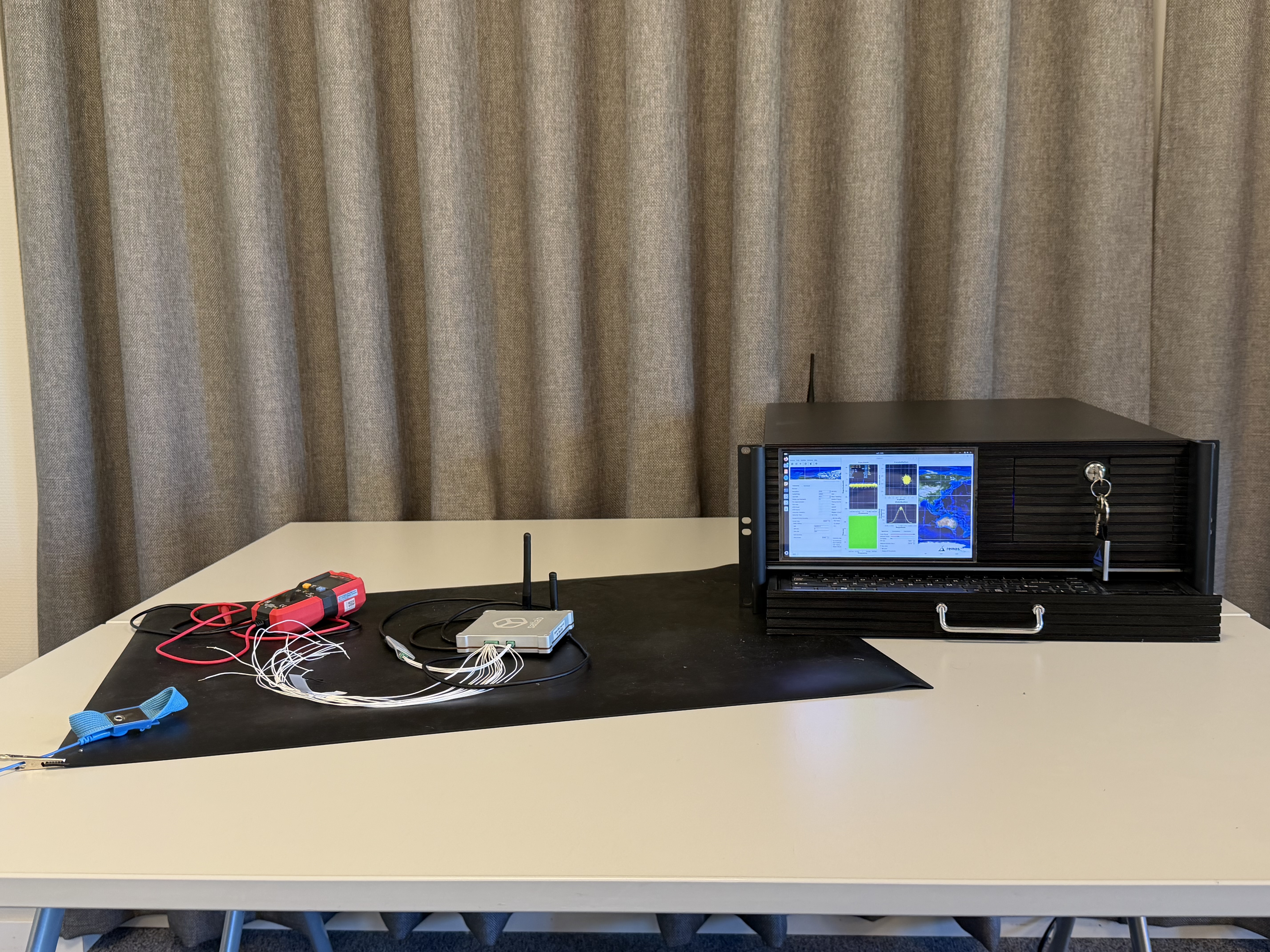
We have been running a lab campaign to validate the Expedite modem against the Satlab SRS-3 S-band transceiver. This post documents what it took to get a clean bidirectional link, from first power-on through a successful CSP ping, including the problems we hit along the way.
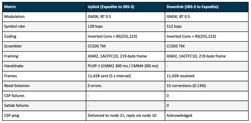
The short version: uplink at 128 ksps GMSK, downlink at 512 ksps GMSK, CCSDS concatenated coding throughout, and the SRS-3 Satlab framing on both sides. The result was 86/86 command frames sent with zero Reed-Solomon errors and 86 telemetry frames received with zero Reed-Solomon, CSP, or Satlab failures. Over an extended run of 11,428 packets sent at 5-second intervals, the uplink delivered every frame without a single Reed-Solomon error. The downlink saw 15 RS corrections across 11,428 frames (a rate of 0.13%) and zero CSP or Satlab failures, confirming the concatenated FEC chain doing exactly what it is designed for.
A first in our lab
We have supported multiple customer satellites that fly Satlab SRS-3 and SRS-4 transponders and have operated those links successfully on orbit. What made this campaign different is that it is the first time we have had an SRS-3 on our bench. Operating a live space link does not give you much room to probe, single-step, or safely provoke edge cases. Having the transceiver in the lab means we could bring it up from cold, capture the spectrum and constellation directly, and exercise the full protocol stack without any time pressure.
This validation is part of a pre-launch compatibility programme we have started at Remos. Satellite manufacturers and subsystem vendors can ship their transceiver (or a complete satellite) to us for a full ground-based interoperability test against the Expedite modem before launch. Finding a framing, FEC, or handshake mismatch on the bench is a lot less stressful than finding it during a live pass you cannot debug.
Test setup
The bench topology was straightforward. The Expedite modem (software-defined, Nano firmware) drove an SDR front end. The SRS-3 was powered from a bench supply and configured over its debug console on /dev/ttyUSB1 at 115200 8N1, connected via tio. The RF link was over the air, with the SRS-3 and the SDR antenna in close proximity in the lab.
Bring-up
The boot loop
On first power-up the SRS-3 console printed a continuous repeating boot banner, which is the classic signature of a brownout reset loop.
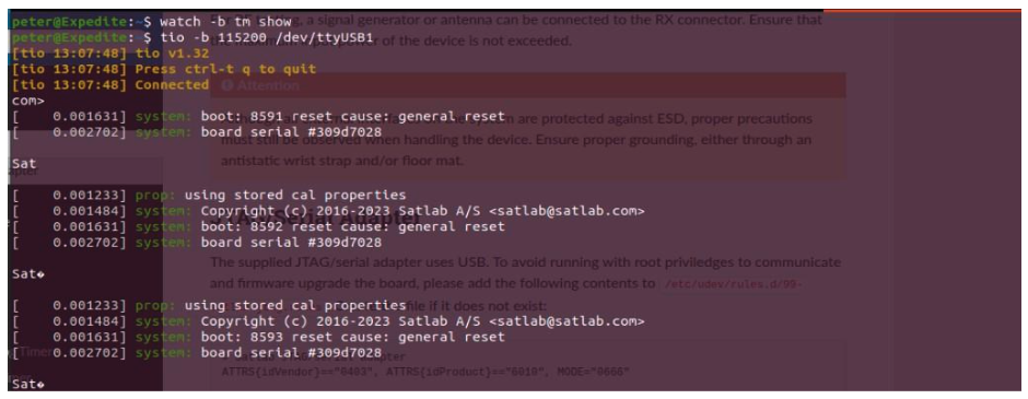
The tell-tale signs were the boot counter climbing every cycle (boot: 8591 -> 8592 -> 8593), each with reset cause: general reset, and the reset happening only about 2 ms into boot, well before reaching the [srs-3] prompt. A general reset that early, on every cycle, points at the supply voltage sagging below the brownout threshold. The board powers up, draws inrush current, the rail collapses, the MCU browns out, and the cycle repeats.
The fix was straightforward. Raising the supply to 10 V (comfortably inside the SRS-3 input range and clear of the brownout knee) stopped the counter and got the board to its shell. The lesson is to verify the voltage at the connector under load, not just at the bench supply.
CSP ping
With the board alive, the next step was a CSP ping. The SRS-3 routing table shows which node lives behind each interface:

csp ping expects a numeric node address, not an interface name. A loopback health check is csp ping 21, and a ping to the peer over the radio targets node 10:

Configuring the Expedite modem
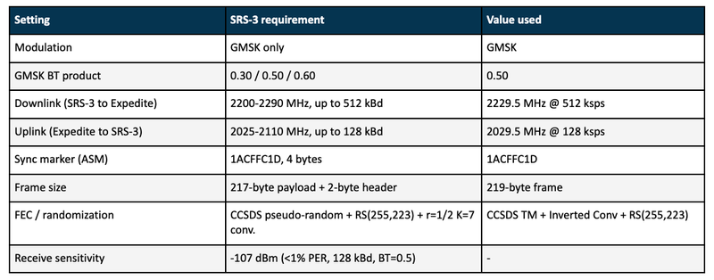
End-to-end interoperability comes down to one rule: every layer on the Expedite side must be the bit-exact inverse of what the SRS-3 expects on air. The SRS-3 framing spec defines a fixed on-air structure: a 4-byte Attached Sync Marker (1ACFFC1D), a 2-byte length/type header, CCSDS pseudo-randomization, and an optional Reed-Solomon (255,223) plus convolutional (r=1/2, K=7) concatenated code.
The most important constraint is that the SRS-3 supports only one modulation: GMSK. Both ends must therefore run GMSK with a matching Gaussian BT product. The SRS-3 allows 0.30, 0.50, or 0.60; we used 0.50. The remaining on-air parameters that need to match are summarised below.
Receiver (telemetry / downlink)
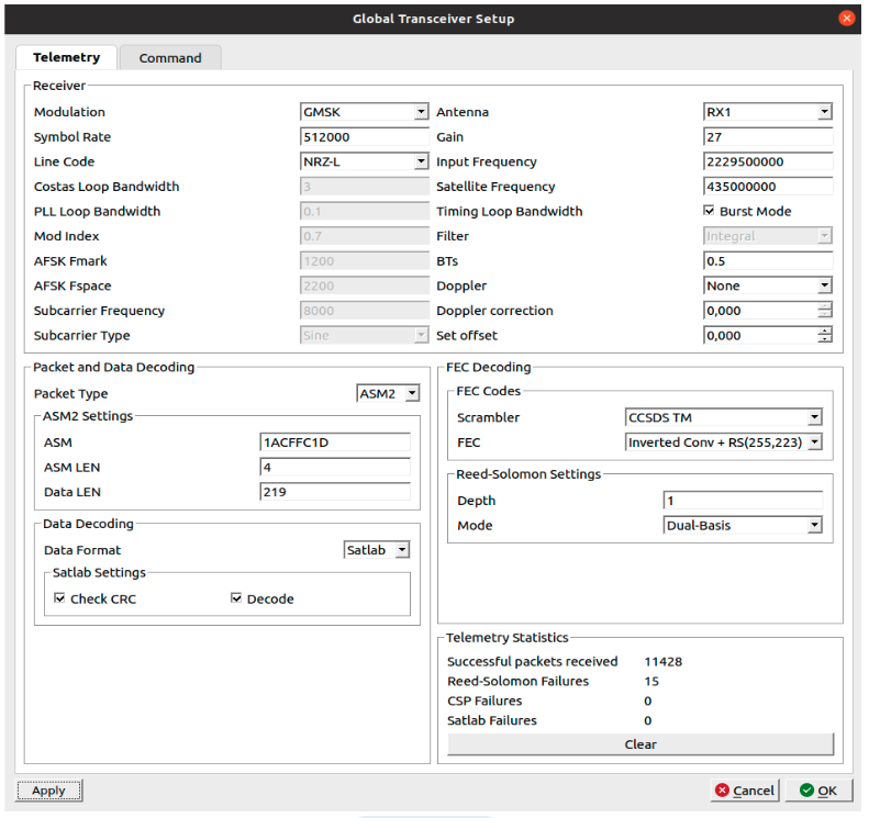
Expedite receiver configuration for the SRS-3 downlink: GMSK at 512 ksps, CCSDS TM scrambler, Inverted Conv + RS(255,223), ASM 1ACFFC1D, Satlab data format -- 11,428 packets received, 15 RS corrections, 0 CSP/Satlab failures
The downlink is the SRS-3 high-rate direction, so the Expedite receiver is set to 512 ksps GMSK with BT 0.5 and NRZ-L line code to match. Input frequency is 2229.5 MHz, with Doppler correction disabled.
One of the more demanding aspects of this link is that the SRS-3 downlink frame begins with only an 8-byte preamble (0x55 0x55 0x55 0x55 0x55 0x55 0x55 0x55) before the ASM and payload arrive. At 512 ksps that is just 125 microseconds of acquisition time. A conventional continuous-tracking receiver would struggle to converge its timing and carrier loops from a cold start in that window.
This is exactly the scenario the Expedite Burst Mode is designed for. Visible in the receiver screenshot as the checkbox next to the Timing Loop Bandwidth field, Burst Mode switches the demodulator into a fast-acquisition regime that widens the timing loop bandwidth at the start of each burst, allowing the receiver to lock symbol timing and carrier phase within the short preamble before the ASM arrives. Once lock is achieved, the loop bandwidth is tightened for low-noise tracking of the payload data. Without this mode, the SRS-3 downlink would be unreliable at its default preamble length.
From Packet Type downward the settings mirror the SRS-3 transmit framing. Packet Type is ASM2 with ASM 1ACFFC1D, ASM LEN 4, and Data LEN 219. The 219-byte data length is the SRS-3 default 217-byte payload plus its 2-byte frame header. FEC is Inverted Conv + RS(255,223) with CCSDS TM scrambler, RS Depth 1, Dual-Basis, which reverses the SRS-3 concatenated coding chain. Data Format is Satlab (Check CRC + Decode), which validates the SRS-3 CRC and strips the framing to recover the CSP packet.
The telemetry statistics confirm a healthy link over an extended run: 11,428 packets received, 15 Reed-Solomon corrections, 0 CSP failures, 0 Satlab failures. The 15 RS corrections represent a frame correction rate of 0.13%, all transparently recovered by the outer RS code with nothing reaching the application layer.
Transmitter (command / uplink)
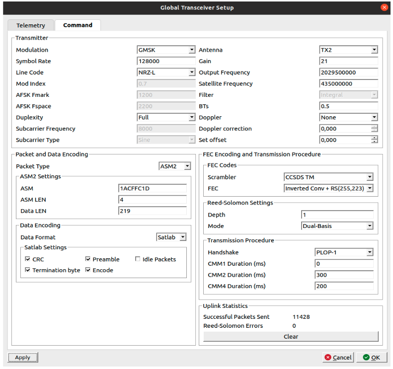
Expedite transmitter configuration for the SRS-3 uplink: GMSK at 128 ksps, Satlab data format with CRC, preamble and termination byte, PLOP-1 handshake with CMM2 = 3000 ms and CMM4 = 2000 ms
The uplink is the SRS-3 receive direction, capped at 128 kbps, so the transmitter mirrors the downlink chain at the lower rate: 128 ksps GMSK, BT 0.5, NRZ-L, output at 2029.5 MHz, same FEC and framing as the receiver.
The Satlab Settings block builds the SRS-3-specific frame. CRC appends the SRS-3 frame CRC. Preamble inserts the 8-byte 0x55 run-in that the SRS-3 spec requires before each uplink frame. Termination byte appends the single 0x00 that flushes the convolutional encoder back to the all-zero state. Idle Packets is left off for single-shot commanding.
Uplink statistics: 11,428 packets sent at 5-second intervals, 0 Reed-Solomon errors.
A note on the FEC
The Inverted Conv + RS(255,223) selection is the CCSDS concatenated code and does two separate jobs. The inner convolutional code (r=1/2, constraint length 7, Viterbi-decoded) cleans up random bit errors from thermal noise. The 'inverted' variant matches the SRS-3 convolutional polarity and resolves the phase ambiguity, so the modem acquires regardless of the received carrier phase. The outer RS(255,223) block code handles any residual burst errors the Viterbi decoder leaves behind. With the settings correctly matched, no RS correction was needed across the entire test run.
Getting the RS basis (Dual-Basis) and depth right is not optional. A conventional-basis or wrong-depth setting produces valid-looking frames that never decode. This is the most common interoperability trap when bringing up a new transceiver.
The recovered signal
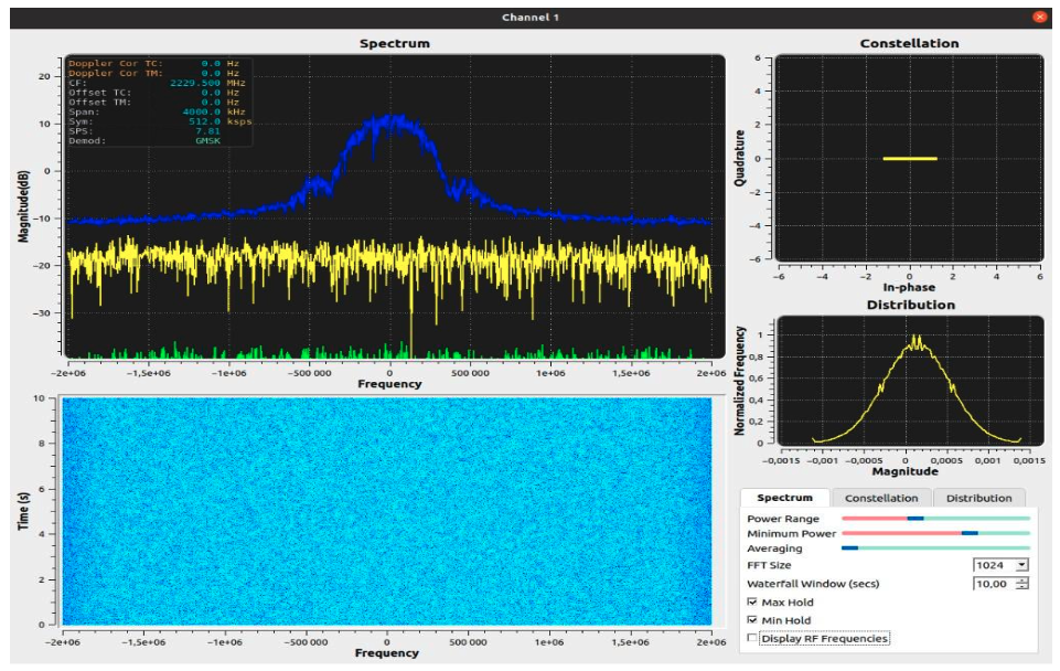
The spectrum view shows the textbook signature of a healthy GMSK link. The power spectrum is smooth and constant-envelope, sitting well above the noise floor. The constellation collapses to a single in-phase lobe, as expected for an MSK-family signal, and the amplitude distribution is the clean bell shape of a phase-modulated constant-envelope carrier.
What is actually in the frame
The diagram below shows the full Satlab frame structure, from the payload down to the on-air bit stream.
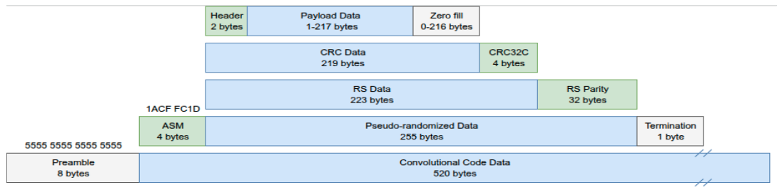
Reading from the top down: the 2-byte header and up to 217 bytes of payload are padded with zero fill to give a fixed 219-byte CRC data block. A 4-byte CRC32C is appended. That 223-byte block is Reed-Solomon encoded, adding 32 parity bytes to produce the 255-byte RS codeword. The 1ACFFC1D ASM (4 bytes) is prepended and a 1-byte termination word is appended before CCSDS pseudo-randomization. The whole thing is then convolutionally encoded (r=1/2, expanding 260 bytes to 520 bytes) and transmitted after the 8-byte 0x55 preamble. Each of these layers maps directly to a setting in the Expedite transmitter configuration.
Underneath all the coding, the command we sent is a single CSP ping to node 21. A CSP v1 header is 32 bits, laid out MSB first: Priority(2), Source(5), Destination(5), Dest port(6), Source port(6), Flags(8). The ping frame 95 50 70 00 00 decodes as follows:
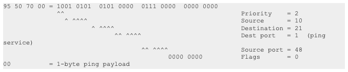
Destination 21 is the SRS-3 own CSP address (the 21/5 LOOP entry in its routing table). Source 10 matches the SRS-3 10/5 SPACE route, so the ping reply routes straight back over the radio. Dest port 1 is reserved for the CSP ping service.
That five-byte frame is what gets CSP-encoded, Satlab-framed, pseudo-randomized, RS- and convolutionally-encoded, and GMSK-modulated. The next section covers what else the transmitter sends around it.
The preamble, and why it is enough
Like any burst receiver, the SRS-3 cannot decode a frame the instant RF appears. It first needs its AGC to settle, then the carrier recovery loop (Costas/PLL) to lock onto the carrier phase and frequency, and then symbol-timing recovery to lock the sample clock. Only then can the frame synchronizer reliably detect the 1ACFFC1D ASM. Transmit the CLTU cold and the loops are still pulling in while the ASM flies past, so the frame is discarded.
The SRS-3 framing spec handles this at the frame level. It mandates a minimum of 8 bytes of preamble (0x55 0x55 ...) before each uplink frame. This is the Preamble setting in the Satlab block on the Expedite transmitter. That byte sequence is transition-dense, which is exactly what the SRS-3 timing and carrier loops need to converge before the ASM arrives. With the preamble in place the link works cleanly, and we confirmed this runs correctly even with the Expedite Handshake set to PLOP-0 (no additional physical-layer run-in).
What PLOP is, and when it is useful
PLOP (the CCSDS Physical Layer Operations Procedure) is a separate mechanism that operates above the frame layer. Rather than inserting a preamble inside the frame, PLOP controls the carrier itself: it can transmit an unmodulated tone, a longer acquisition sequence, and an idle tail around each CLTU. The Expedite implementation supports three modes via the Handshake dropdown.
PLOP-0/None transmits the CLTU with no additional carrier choreography. PLOP-1 wraps each CLTU in a per-burst carrier run-in (CMM-1 unmodulated, CMM-2 acquisition sequence, CMM-3 the CLTU, CMM-4 idle tail). PLOP-2 holds the carrier and acquisition sequence up continuously across many CLTUs, only dropping when the queue empties, which is useful for high-rate bulk uplink.
For the SRS-3 with the Satlab preamble enabled, PLOP-1 adds extra margin on top of what the preamble already provides. The CMM durations can be tuned aggressively: in the extended 11,428-packet run we used CMM2 = 300 ms and CMM4 = 200 ms rather than the more conservative 3000/2000 ms used initially, with no impact on link quality. PLOP-2 is useful if you need to stream many CLTUs back-to-back without a fresh acquisition overhead on each one.
Results
TT&C Visualizer
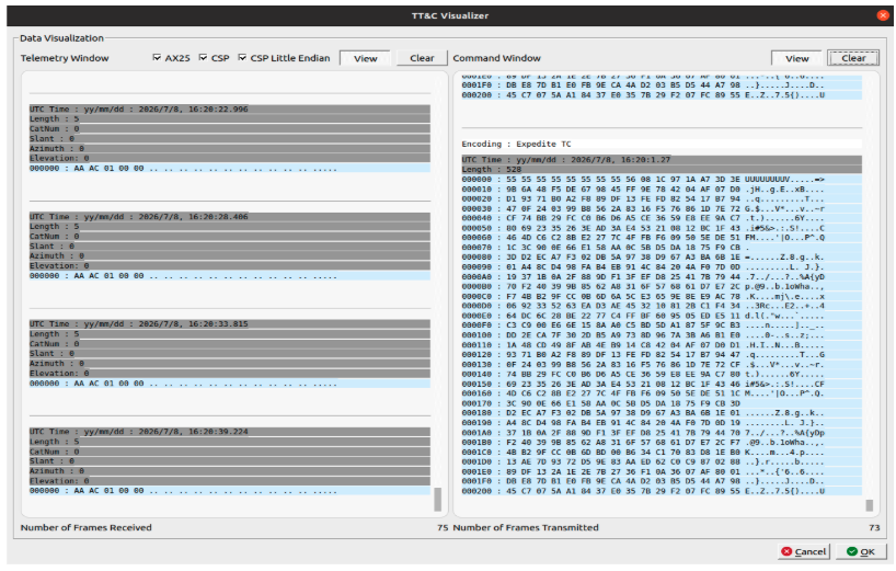
The TT&C Visualizer confirms the link at the application layer. The telemetry window shows CSP ping replies arriving at regular intervals, each with Length 5, CatNum 0, and payload AA AC 01 00 00, which is the SRS-3 response to each command ping. The command window shows the full encoded uplink frame at Length 528, confirming the Satlab preamble, CLTU, and CCSDS coding chain assembled correctly. 75 frames were received and 73 frames transmitted over the test run.
Analysis
The extended run gives a much more meaningful picture of link quality than the initial short test. Zero Reed-Solomon errors across 11,428 uplink frames means the SRS-3 receiver was locking and decoding every command without any FEC intervention throughout. On the downlink, 15 RS corrections across 11,428 frames is a correction rate of 0.13%, and with 0 CSP and 0 Satlab failures every one of those frames was recovered transparently at the application layer. This is the concatenated FEC chain working as designed: the outer RS code silently absorbs the occasional burst error that the inner Viterbi decoder leaves behind.
The asymmetric symbol rates (128 ksps up, 512 ksps down) match the SRS-3 limits: 128 kbps maximum receive, 512 kbps maximum transmit. The modem is exercising the transceiver at its rated envelope. It is also worth noting that the PLOP-1 CMM durations were reduced to 300/200 ms from the initial conservative 3000/2000 ms with no degradation, which significantly reduces the RF-on time per command in a real mission scenario.
Takeaways
For anyone bringing up a similar link: match the SRS-3 framing exactly (ASM 1ACFFC1D, 219-byte frames, CCSDS TM scrambling, dual-basis RS(255,223) with the inner convolutional code) and enable the Satlab preamble. The 8-byte 0x55 run-in is what gives the burst receiver time to acquire before the ASM arrives. Enable Burst Mode on the Expedite receiver to handle the short preamble window. If using PLOP-1, the CMM durations can be kept short: 300/200 ms worked cleanly over 11,428 packets. Also feed the board a stiff supply; brownout loops look like firmware faults but are almost always power.
Future work includes testing AES-256-GCM encryption on the SRS-3 link, pushing to higher throughput configurations, and validating over an over-the-air path with Doppler correction enabled.
Pre-launch compatibility testing
This SRS-3 campaign is the first published result from the Remos pre-launch end-to-end compatibility programme. If you are a satellite manufacturer or subsystem vendor and want to test your transceiver (or complete satellite) against the Expedite modem before launch, get in touch. We can confirm framing, FEC, and physical-layer handshake compatibility on the ground rather than discovering mismatches during a live pass.
References
Satlab SRS-3 S-band Transceiver Datasheet, rev 1.3
CCSDS 131.0-B-3, TM Synchronization and Channel Coding, 2017